What this source text corrects
This source text resolves the identity of jacarfig.gif, an image referenced by the source capture of the Karrick dossier page 1jacar.htm. The image is not an isolated or decorative graphic. It is Figure 2 of a thesis-style report on processing Utah cannel coal, and it is explicitly captioned in the surrounding text as "a schematic plant layout" of the small distilling plant built for that study. Figure 3, described in the same passage, is a photograph of the test setup.
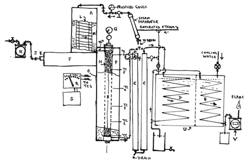
The correction matters because the figure has previously been treated as an unattributed image. Grounding it in the apparatus description lets the wiki state what the drawing actually depicts — a labelled process schematic — and keeps it separate from the performance claims that appear elsewhere in the same report.
The report the figure belongs to
The captured text is a section-by-section report with a numbered table of contents: acknowledgement, introduction, cannel coal, Utah's cannel coal deposit, object of plant tests, description of apparatus, general test procedure, description of individual tests, heat calculation for Test Run #6, discussion of results, summary and bibliography. Several sections are marked "[Not included here]" in the capture, so the excerpt is a boundary rather than the whole document.
The stated object of the plant tests was practical. A 1932 visit to the cannel coal deposit found it extensive and accessible enough by truck and rail to justify early development, and the coal was judged superior to other local coals for domestic fuel and as a source of road oil and motor fuel. The authors therefore planned a study of the heat requirements for treating slack coal from the deposit, together with an investigation of the products formed.
The report states that the study took advantage of laboratory processing data obtained in 1920 by the State of Utah and the Federal Government, and that "excellent yields and quality of oil were obtained" in that earlier work. That statement is an assertion about the 1920 studies, not a result of the 1933 test plant and not something the schematic figure demonstrates.
The process attributed in the text
The destructive distillation method described used steam as the heat-transferring fluid: exhaust steam from power plant engines or turbines was superheated and then passed directly through bodies of sized, dust-free coal. The report identifies this as the Karrick LTC Process, notes that it had subsequently been developed for commercial uses, and says it was adapted for the thesis study of the cannel coal. The text further states that the coal-treating method used "is one of a group being offered to the Utah Research Foundation [by Lewis C. Karrick]".
Two design objectives are stated for the test apparatus: minimize radiated heat losses under all processing conditions, and take temperature and heat-flow data throughout the coal charges and the apparatus so that products obtained could be correlated with the most economical use of heat.
What Figure 2 depicts
The figure is a labelled schematic of the process apparatus. Read together with the text, it shows a pressure gauge, a steam separator, a vertical heated vessel marked with thermocouples, a cooling-water inlet, paired zigzag condenser passages, drains and a flare outlet, with arrows indicating flow direction. It is a schematic — not a photograph, and not a table of measured performance.
The plant, as the text describes it, consisted of a gas-fired superheater (a), a coal retort (b), and the condensers (c), (d) and (e).
Apparatus details as stated in the source
The description of apparatus gives the following component-level detail. These are the report's own specifications for the test rig.
| Component | Description as stated |
|---|---|
| Superheater combustion chamber (f) | Common brick |
| Gas supply | Control valve (g), meter (h), manometer (i) for instantaneous sight control of gas volume to the two burners |
| Burners | Nozzles (j) and air/gas mixing tubes (k) |
| Steam superheating coil | Approximately 100 ft of 1/2" standard pipe, formed into a coil 15" in diameter and 48" high |
| Coil placement | Hung in the annular space between the cylindrical column (l) and the heat-insulating outer wall (m); hot combustion gases pass at high velocity over the coil counterflow to the steam |
| Outer wall (m) | 4" thick, two sheet-metal casings filled with diatomaceous silica earth; supported on a framework about 10 ft above the floor |
| Coil inlet fittings | Steam gauge, steam-flow regulating valve, and a steam separator with a drain |
| Retort (b) | Thin-walled cylinder (n) of 18-gauge black iron, welded seams, 5" diameter × 8 ft high |
| Retort closures | 5" pipe couplings welded at top and bottom with screw plugs as removable closures |
| Retort-to-superheater connection | Flexible multiple-elbow assembly of 1/2" fittings and nipples; retort suspended from a wall bracket by wires to arms welded to its top, so length changes occur downwardly |
| Vapor outlet | Flexible multiple-elbow outlet of 3/4" fittings at the bottom of the retort, leading into condenser (c) |
| Retort insulation | Sheet-iron jacket (o) spaced 6" from the retort, annular space (p) filled with diatomaceous earth; insulation and jacket supported 2 ft above the floor by a circular steel plate |
| Thermal-expansion provision | Lower 4" of the retort and the vapor connections protrude through the support plate, allowing free vertical movement |
The flexible connections at both the top and bottom of the retort are described as relieving strains caused by changes of length with temperature.
Cannel coal as characterized in the report
The report's section on cannel coal quotes two authorities. Ashley (ref. 11) defines cannel coal as a massive, non-caking, tough, clean block coal of fine, even, compact grain, dull lustre, commonly conchoidal cross fracture, with a low fuel ratio, a high percentage of hydrogen, easy ignition, a long yellow flame, a black to brown greasy streak, and moderate ash that is pulverulent in burning. Ashley describes it as essentially a rock derived by solidification and partial distillation or oxidation of water-laid deposits containing large quantities of plant spores and pollen grains, with more or less comminuted remains of low orders of water plants and animals.
David White (ref. 12), writing on his microscopical study of the Utah cannel coal, reports that the fuel contains very little if any vestiges of the cell structures of higher plants, being made up largely of lemon-yellow, more or less lenticular or globular, translucent bodies embedded in a brownish black groundmass of somewhat flocculent aspect. White notes that some of the translucent matter is probably resinous, that some of the lemon-yellow substance may be gelatinous though this is not certain, and concludes that the microscopical composition is essentially that of a high-grade cannel.
The report adds the general observation that bituminous coals are generally accepted to have resulted from woody materials, whereas cannel coals appear to have been formed from decayed spores, pollen, leaves and cuticle material from plants.
Limitations and unresolved questions
- The "excellent yields and quality of oil" statement belongs to the 1920 State of Utah / Federal Government laboratory studies as reported in this text. It is not a result of the 1933 test plant, and the schematic figure does not establish it.
- Figure 2 is a schematic. Any reading of it as a record of measured performance, oil quality or heat economy would be unsupported by the figure itself.
- The capture is an excerpt boundary. Sections 1, 2 and 4 are marked "[Not included here]", and the excerpt ends mid-sentence in the apparatus description. Absence of later results within this excerpt is not evidence that such results do not exist in the full document.
- Whether Figure 3, the photograph of the test setup, is separately captured and should be linked to this page remains open.
Related work in the archive
This source text sits alongside the other Karrick dossier packets already in the wiki, including the earlier treatment of the same figure identifier and the packets covering the Karrick retort figure and the uncaptioned karrick*.gif files. It also connects to the broader fuels and chemistry topic guides.
Source notes & attribution
- Source capture: https://rexresearch.com/karrick/1jacar.htm (Rex Research Karrick dossier, 1jacar.htm ), including the mirrored copy at https://rexresearch1.com/CoalMiningLibrary/karrick/1jacar.htm .
- Figure file: https://rexresearch.com/karrick/jacarfig.gif (Figure 2, schematic plant layout).
- Ashley (ref. 11) — definition of cannel coal, quoted in the report.
- David White (ref. 12) — microscopical study of Utah cannel coal, quoted in the report.
- Reference (9) — 1920 State of Utah and Federal Government laboratory processing studies.
- Reference (13) — the Karrick LTC Process.
- https://rexresearch.com/karrick/1jacar.htm
- https://rexresearch.com/karrick/1larstz.htm
- https://rexresearch.com/karrick/karric.htm
- https://rexresearch.com/karrick3/karrick3.htm
- https://rexresearch1.com/CoalMiningLibrary/karrick/1jacar.htm
- https://rexresearch1.com/CoalMiningLibrary/karrick/1larstz.htm
- https://rexresearch.com/karrick/1ketch.htm
- https://rexresearch.com/karrick2/kltcusp.htm
- https://rexresearch.com/ketchum/1ltcre.htm