This the source archive dossier reproduces BIOS Final Report No. 1043, "The Invention of Hans Coler, Relating to an Alleged New Source of Power," written by R. Hurst of the British Ministry of Supply with Captain R. Sandberg of the Norwegian Army, and dated 1946. The report is an Allied intelligence document: it records the interrogation of the German inventor Hans Coler and his financial backer Dr. F. Modersohn, the on-site construction and testing of a small model of Coler's device, and the appended 1926 test reports of two German professors. The dossier then adds a reception layer — later papers, patents, forum research and replication attempts — that is not part of the 1946 report.
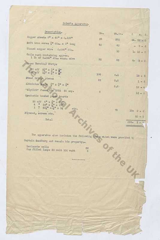
The subject is a claimed new source of energy. Coler built two devices: the Magnetstromapparat (a static arrangement of permanent magnets, copper coils and condensers) and the Stromzeuger (a battery-excited magnet/coil/copper-plate machine that he claimed could deliver roughly 6 kW indefinitely from a few watts of dry-battery input). The report's own investigators judged Coler honest, judged the small effect they observed to be genuine "in so far as could be tested," and could not explain it. Their own four laboratory experiments, however, failed to confirm the individual sub-effects on which the claimed mechanism depended, and they concluded that earlier successes were due to "chance, or happy accident."
This is a historical intelligence report plus a patent and forum-adjacent account. It is not independent validation of an over-unity energy source, and nothing in the dossier supplies a measured energy balance that survives scrutiny.
What the report is and how it was produced
BIOS (British Intelligence Objectives Sub-Committee) reports were post-war technical interrogations of German industry and science. Report No. 1043 has the following structure, as reflected in the dossier:
- Front matter, Sections I–IV: object of the visit, historical notes, interrogations, construction and testing, conclusions.
- Appendix I: Coler's own summary of the Stromzeuger principle.
- Appendix II: Prof. M. Kloss's test report of March 1926.
- Appendix III: Prof. W. O. Schumann's test report of March 1926.
- Appendix IV: the Coler & Frohlich report to the O.K.M. (Oberkommando der Marine), 1943 — reproduced only partially in the dossier.
- Appendix V: an extract from Coler's 1943 statement on Frohlich's experiments.
- The full text of German patent DE680761.
- A closing aggregation of later commentary, papers, patents and forum posts.
The dossier notes that Appendices IV and V are not fully available and that Figures 1–4 are not reproduced.
The two devices
Magnetstromapparat
The Magnetstromapparat ("magnet current apparatus" or "magnetic power apparatus") is described as a static device: six permanent magnets wound so that the electrical circuit includes the magnet itself, arranged in a hexagon with two small condensers, a switch, and two nested solenoidal coils, one sliding inside the other. It has no battery. It is brought into operation by trial-and-error adjustment of the magnet separation and the position of the sliding coil.
Coler stated that the greatest tension he obtained from the Magnetstromapparat was 12 volts, and that the magnet strength did not decrease during use.
Stromzeuger
The Stromzeuger ("generator") is a magnet, flat-coil and copper-plate arrangement with a battery-excited primary circuit. Coler claimed it could give 6 kW output indefinitely from a few watts of dry-battery input. No working example existed at the time of the 1946 report; Coler offered to build one, and the BIOS team recommended that the offer be taken up.
Coler's own theory
Coler could give no coherent theory. He suggested that ferro-magnetism oscillates at roughly 180 kHz in the magnetic circuit, and that he was tapping what he called "Raumenergie" (space-energy). Appendix I describes a "separation of charges," "magnetically polarized" charges, and a flow of "space electrons" between "repelling spaces" and "attracting spaces" — an element the BIOS reporter explicitly could not follow.
The 1926 test reports
Kloss, 3 March 1926
Prof. M. Kloss of Berlin tested the Stromzeuger on 3 March 1926, with Prof. Dr. R. Franke of the Technical College of Berlin present. The apparatus had double-row copper plates, double-row flat spools, and an electromagnet system with silver wires on cores, powered by three 6 V / 6.5 Ah accumulator batteries. Kloss's measurement table is reproduced verbatim below.
| Nr. | Test | Charge | Magnet Circuit | Plate Circuit | Spool Circuit | External Circuit |
|---|---|---|---|---|---|---|
| 1 | Instr. built-in | 0 | 0.21 A / 0.5 V | — / 6.4 V | — / 6.3 V | — / 6.0 V |
| 2 | Instr. built-in | 2 bulbs | 0.21 A / 0.5 V | 0.16 A / 4.7 V | 0.16 A / 4.3 V | 3.1 A / 3.5 V |
| 3 | Instr. built-in | 3 bulbs | 0.21 A / 0.5 V | 0.22 A / 4.0 V | 0.075 A / 3.45 V | 3.7 A / 3.0 V |
| 4 | Instr. built-in | 3 bulbs | — | 0.215 A / 4.0 V | — | 3.7 A / 3.0 V |
| 5 | S&H 423820 | 3 bulbs | — | 0.215 A | — | — |
| 6 | Instr. built-in | 3 bulbs | — | — | 0.08 A / 3.4 V | 3.7 A / 3.0 V |
| 7 | S&H 423820 | 3 bulbs | — | — | 0.070 A | — |
| 8 | Instr. built-in | — | 0.21 A / 0.5 V | — | — | — |
| 9 | S&H 423820 | — | 0.2 A | — | — | — |
| 10 | Instr. built-in | 3 bulbs | — | — | — | 3.3 A / 3.0 V |
| 11 | S&H 423820 | 3 bulbs | — | — | — | 3.08 A / 2.3 V |
| 12 | S&H 254159 | 3 bulbs | — | — | — | 2.95 A |
| 13 | Instr. built-in | 2 bulbs | — | — | — | 3.15 V |
| 14 | S&H 423820 | 2 bulbs | — | — | — | 3.15 V |
| 15 | Instr. built-in | 1 bulb | — | — | — | 4.1 V |
| 16 | S&H 423820 | 1 bulb | — | — | — | 4.45 V |
With three bulbs, Kloss recorded plate plus spool battery current of 0.215 + 0.070 = 0.285 A, while the bulbs consumed about 3.5 A at about 2.3 V. On that basis he computed roughly 1.7 W in against roughly 8 W out — a power ratio of about 4.7× (the source's "about 12 times" figure refers to the current in the bulb circuit versus the current from the two batteries, not to power). Kloss could not explain the energy source; he conjectured that the magnet system was the source, and recommended building a larger apparatus with built-in instruments. He also asked whether the magnets wear out; the dossier does not record an answer.
Schumann, 19–20 March 1926
Prof. W. O. Schumann of Munich tested the apparatus on 19–20 March 1926. With two bulbs he recorded plate battery 48 mA, spool battery 39 mA and exciter battery 170 mA, giving a total battery capacity of 0.257 × 6 = 1.542 W, against bulbs at about 3 A × 3.5 V = 10.5 W — a ratio of about 6.7×. With one bulb: plate 28 mA, spool 23.5 mA, exciter 180 mA, giving 6 × 0.232 = 1.392 W against a matched bulb at 4.5 V × 1.5 A = 6.75 W — a ratio of about 4.85×. Schumann wrote "I do not believe in a deception" and surmised "a new source of energy."
Schumann also noted that the spool circuit alone drew 104 mA, dropping to about 27 mA when the plates and exciter circuit were also switched on. His tension measurements across the two halves of the plate-spool winding were markedly unequal:
| Winding (top→down) | Right Side | Left Side |
|---|---|---|
| 1 | — | 0.34 |
| 2 | 0.24 | — |
| 3 | … | 2.8 |
| 4 | 2.6 | — |
| 5 | 8.4 | 12.4 |
| 6 | 24 | 22 |
| 7 | 22 | 28 |
| 8 | 24.6 | 100–140 |
| 9 | 26 | 46 |
| 10 | 25 | 30 |
Values are in millivolts. The asymmetry — up to 100–140 mV on the left side at winding 8 against about 24.6 mV on the right — is one of the few quantitative anomalies in the dossier, and it is not explained.
The BIOS team's own construction and test (1946)
The team built a small Magnetstromapparat. After three days of fruitless adjusting, a first deflection appeared at about 9 a.m. at roughly 7 mm magnet separation. With the switch closed, the reading reached 250 mV by 11 a.m. and 450 mV by 12.30 p.m., and was maintained for about three hours until a soldered tag disconnected; the meter then dropped to zero, and resoldering did not restore the tension. A repetition recorded as 7.24.46 gave 60 mV after about three hours, maintained for more than 30 minutes, then falling to zero on further adjustment.
The team noted that the model was completely open and could be picked up, moved, tilted and turned without effect, and that the nearest mains cable was at least six feet away. They described the result as, "for the moment, inexplicable."
Their conclusions: Coler was honest and not a fraud; the result was genuine "in so far as could be tested"; no explanation was attempted; further investigation by an expert in electromagnetic theory was warranted; and Coler's offer to build a Stromzeuger should be taken up. The report also observed that a claim of this kind would normally be considered fraudulent.
The report's four laboratory experiments
The technical core of the report describes the apparatus as three inter-wound, inter-coupled circuits — anchor (Anker), field (Feld) and directing (Steurkreis) — with the anchor as the presumed site of energy gain. The large coil plate is the Plattenspule (plate spool); paired Flachspule (flat coils) are interwound in two groups acting as transformer primary and secondary. The basic diagram is a condition of self-interruption (Selbstunterbrechung): plate discharge interrupts the battery current in the field circuit, which in turn interrupts the directing circuit, recharging the plates cyclically. The report invokes the Barkhausen effect to give each process its impulse-like character and the necessary phase change, and lists this as an unsolved problem.
The team then tested the sub-effects directly:
- Winding-direction effect. Whether right- and left-handed coils build up their fields at different rates. Apparent resistances of ten right- and ten left-handed coils were equal within ±1%, and induced secondary potentials measured with a cathode-ray oscillograph were equal. Conclusion: no such effect exists.
- Magnet rectification. A pre-magnetized steel rod in series with a secondary winding was expected to rectify. Tested only at audio frequency, no phenomenon was observed with instruments or oscillograph. The question was left open for high-frequency impulse-like fields.
- 1937 Hingst two-solenoid secondary DC. Coler and Dipl. Ing. Rudolf Hingst had reported a considerable direct-current component in a secondary circuit whose two halves should cancel. The BIOS team's test did not confirm it.
- Plate / flat-coil interactions. The 0–12 kHz oscillator was insufficient to measure plate mutual influence, so a valve-voltmeter oscillograph was used. The team found that the anchor tracts are not all one oscillating circuit; each plate–coil–plate group is an independent circuit — ten such circuits — whose individual frequencies could not be measured. The flat coils showed about 200 Ω apparent resistance at 10 kHz despite 25 mm spacing, and a transfer factor of 0.85, maximal at 10 kHz.
The report's verdict: "The success of the inventor up to now could only be due to chance, or happy accident." No technical means were available to make the necessary tuning adjustments.
The 1943 Coler & Frohlich statement
Appendix V carries an extract from Coler's 1943 statement, dated Berlin, 27 September 1943, describing experiments by Dr. H. (Heinz) Frohlich. The apparatus used a 1:1 transformer, an iron-free flat-coil inductor, a Bosch ignition-magnet interrupter at 100 Hz, a reversible rectifier, a hot-wire ammeter and a thermopile. Coler claims a "clear proof" that the opening (intake) impulse carries more energy than the closing impulse — about 50% by thermal measurement and about 10% by planimetric measurement of Siemens loop-oscillograph traces. Coler argues that the smaller oscillographic figure is explained by instrument lag, and treats the result as proof of his "Space Energy Receiver."
The same 1943 material records that the apparatus was developed empirically between 1923 and 1926, that it delivered higher output than input, that success in starting depended on a "happy accident," that the O.K.M. supported the work, that the aim was to demonstrate a working apparatus to the Führer before measuring, and that the newly developed apparatus could not be made to work because of its complexity.
German patent DE680761
The dossier reproduces the full text of DE680761, "Anordnung zur Umwandlung von Gleichstrom in Wechselstrom" (Arrangement for converting direct current into alternating current).
Title:      Anordnung zur Umwandlung von Gleichstrom in Wechselstrom
Inventor:   COLER HANS
Applicant:  FRITZ MODERSOHN DR ING
CPC:        H02M1/20
IPC:        H02M1/20
Date:       1939-09-07
| Element | Description |
|---|---|
| U1, U2 | Two direct current sources |
| R1, R5 | Series-connected auxiliary resistors between negative poles |
| R2, R4 | Series-connected auxiliary resistors between positive poles |
| V1, V2 | Consumer (load) resistors, in series with the auxiliary resistor pairs |
| R3 | Bridge resistor between points B and C |
| S1 | On/off switch in series with R3 |
| S2 | Periodically operating interrupter between positive pole D of U2 and negative pole A of U1 |
| W | Annular closed resistor of interrupter S2 |
| K | Rotating contact lever over W |
| E, F | Connection point and maximum-resistance point on W |
The patent claims generation of AC of any frequency and waveform from DC, with pure DC, chopped DC and pure AC extractable simultaneously. Frequency equals the number of S2 make-break cycles per unit time; subdividing the resistance ring multiplies frequency. In the worked example, W = 20,000 Ω gives a maximum resistance between A and D of 2,000 Ω (the conductor part practically interrupted); one revolution of K is one period; with four connection points E1–E4 one revolution yields four periods, so 100 rev/s gives 400 Hz; with six subdivisions and 100 rev/s, 600 Hz.
This is a conventional DC-to-AC conversion patent. It contains no over-unity claim. The dossier does not explain the relationship between this patent and the energy-surplus claims.
Instruments used
| Instrument | Use |
|---|---|
| Phillips-Schwebungs-Summer (0–12 kHz) | Apparent resistance; excitation |
| Siemens & Halske cathode-ray oscillograph | Induced potentials (Experiment 1) |
| Highly sensitive oscillograph as valve voltmeter | Plate potentials (Experiment 4) |
| Siemens loop oscillograph | Frohlich experiment recording |
| Thermopile + sensitive milliammeter | Frohlich energy measurement |
| Bosch ignition magnet interrupter (100 Hz) | Make-and-break in Frohlich experiment |
The 1926 tests used a Siemens & Halske precision DC instrument Nr. 423820, a Hartmann & Braun hotwire instrument Nr. 254159, a Hartmann & Braun millivoltmeter Nr. 462375, and an A.E.G. turn-spool millivoltmeter. Kloss and Schumann used hotwire instruments specifically to determine whether the output was continuous current or wave current.
The reception and replication layer
The dossier's final section is not part of the 1946 report. It collects later commentary and replication attempts.
- hyiq.org claims Coler's surname was actually spelled "Coeler," citing his sister Ursula, and glosses the device names.
- A promotional blurb for a book ("Free Energy Conspiracy World") asserts that Coler's generator captured energy from Earth's magnetic field, that a 1937 Berlin University demonstration failed replication, that Coler was accused of fraud, forced to reveal the device, and that it was seized by the government. This conflicts directly with the BIOS report's finding of Coler's honesty.
- Thorsten Ludwig published two papers on the Coler devices (2011, Physics Procedia 20:446–456; 2012, "The Inventions of Hans Coler").
- Claus Wilhelm Turtur published a viXra paper (1109.0022v1) on the zero-point energy of the electromagnetic quantum vacuum and attempted a Magnetstromapparat reproduction. He claims both Coler engines exceeded 100% efficiency and that demonstrations at Berlin, München, Trondheim and Kopenhagen confirmed more output than input. His own reproduction, after extensive adjustment, gave a reproducible machine power of about 25 mW; the output was AC, not the DC Coler described; Fourier analysis showed a wide frequency band with strong contributions from local radio transmitters; and a shielded room produced no serious signal. Turtur could not determine the functioning principle and cancelled the analysis.
- George Hathaway reported a 1981 reproduction attempt presented at the Canadian "First International Symposium on Non-Conventional Energy Technology," giving about 50 mV.
- "Smudge", posting on overunityresearch.com, reports UK National Archives research and claims the Stromzeuger was based on the Norrby device, and that Coler was contracted to work in the UK to replicate the Stromzeuger but died of a heart attack before claiming success. Smudge proposes a mechanism family based on the Corbino effect and the anomalous Hall effect (AHE), with soft iron cores in which conduction electrons can become spin-polarized, and a Larmor precession / cyclotron frequency charge-pump hypothesis. Smudge's own 2005 Stromzeuger layout description is acknowledged as incorrect.
- A forum experimenter ("Peter") reports a test with a 2.5 V amplitude (5 V pk-pk) DDS drive at 180 kHz on an iron rod with a magnet: flipping the magnet changed the average pk-pk from 329 mV to 322 mV, about a 7 mV difference, reproducible across trials. A follow-up series of nine tests gave values ranging 306–334 mV with no clean monotonic pattern.
- WO1994001814A1 ("Enhanced transformer") claims an inductive device with an amorphous-metal core enhanced by a permanent magnet enables increased electrical energy output; its background cites Coler's research as the origin of solid-state permanent-magnet generation.
- US3089995 ("Hall-effect apparatus"), assigned to Bell Telephone Labs, follows D. A. Kleinman and A. L. Schawlow's 1960 prediction of self-oscillation in a Corbino disk. The patent claims negative resistance, not over-unity.
- A Chinese-language PDF links Coler's generator to the "Haunebu" flying saucer myth. The dossier asserts this connection without support.
- A pseudonymous replicator ("Michel") posted a partial Magnetstromapparat build on overunity.com; only a build photo is shown, with no results.
Limitations, contradictions and unresolved questions
- No independent replication with a credible energy balance. The BIOS team's own four experiments failed to confirm the claimed sub-effects, and their own device produced only millivolt-level, non-reproducible output.
- The energy source is unidentified. The report states it is "not explainable by existing scientific theories."
- The 1943 statement contradicts the 1946 tests. Coler asserted a proven energy difference; the BIOS team could not reproduce the apparatus working.
- The 1926 and 1946 tests may not concern the same device. The relationship between the Stromzeuger tests and the Magnetstromapparat test is not established.
- The Barkhausen effect's assigned role is untested, and the individual frequencies of the ten oscillation circuits were never measured, so the required mutual resonance condition is unverified.
- DE680761 makes no over-unity claim, and its relationship to the energy-surplus claims is unexplained.
- Turtur's AC output contradicts Coler's DC claim, and his shielded-room null result is ambiguous — it could indicate zero-point shielding or simply radio-frequency exclusion.
- A skeptical alternative exists: the silk-covered copper wire battery-effect hypothesis, in which the Magnetstromapparat's anomalous output arose from a damp-atmosphere battery effect between silk-covered copper wire and a conductive permanent magnet. The dossier records this as a competing explanation.
- The fraud narrative and the honesty finding cannot both be right. The book blurb's cover-up story conflicts with the BIOS assessment.
- The Norrby claim is unconfirmed in the material reproduced here, and the UK National Archives material (about 188 JPEG images) is not reproduced.
- The "Coeler" spelling is asserted from a family source and is not corroborated by the report itself.
Related work
The dossier connects to a wider literature on claimed permanent-magnet and solid-state energy generation, to the Corbino and Hall-effect literature invoked by later commentators, and to the zero-point energy framing used by Turtur. Within this wiki, see comparison-coler-claims-vs-evidence for a structured comparison of the claims and the evidence, and the entity and concept pages linked above for the individual devices, people, patents and mechanisms.
Source notes & attribution
- BIOS Final Report No. 1043, "The Invention of Hans Coler, Relating to an Alleged New Source of Power," R. Hurst (Ministry of Supply) with Captain R. Sandberg (Norwegian Army), 1946. Reproduced at rexresearch.com.
- Appendix II: Prof. M. Kloss, test report dated 4 March 1926 (tests of 3 March 1926).
- Appendix III: Prof. W. O. Schumann, test report dated 3 April 1926 (tests of 19–20 March 1926).
- Appendix IV: Coler & Frohlich report to the O.K.M., 1943 (partial).
- Appendix V: extract from Coler's statement, Berlin, 27 September 1943.
- DE680761, "Anordnung zur Umwandlung von Gleichstrom in Wechselstrom," inventor Hans Coler, applicant Dr.-Ing. Fritz Modersohn, filed 1939-09-07.
- T. Ludwig, Physics Procedia 20 (2011) 446–456; "The Inventions of Hans Coler" (2012).
- C. W. Turtur, viXra:1109.0022v1.
- WO1994001814A1, "Enhanced transformer."
- US3089995, "Hall-effect apparatus" (Kleinman / Schawlow, Bell Telephone Labs).
- https://rexresearch.com/coler/colerb.htm