The inter-atomic ion motor
What survives in the patent and newspaper record?
Start here / 12 minute read
Antonio d'Angelo: The Inter-Atomic Ion Motor, the 1928 NYT Report and US 2,021,177
This source dossier combines two documents about the same claimant: a New York Times report of Wednesday, March 7, 1928, headlined "Priest Has Motor Run By 'Ion Energy'", and the specification of US Patent 2,021,177, "Motor Generator & Other Transformer," granted November 19, 1935. The two documents describe the same inventor, the Rev. Antonio d'Angelo, S.J., but they describe very different things. The newspaper account reports an announcement of a motor that generates "many times the power it receives originally from an electric battery" using "inter-atomic" energy. The patent describes an electromagnetic motor-generator and rotary transformer with a specific winding geometry, and does not claim over-unity at all. The gap between the two is the most important feature of this source.
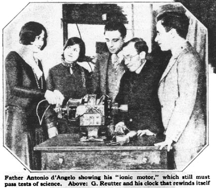
The dossier also carries a photograph credited to Popular Science Monthly (July 1928, p. 26) and a set of patent figures (Figs. I–XV) reproduced as images.
The 1928 press claim
The Times article reports that d'Angelo, an Italian Jesuit missionary working at Ribeirão Preto, Brazil, announced in New York a motor using "interatomic" energy. The article states the motor was then in Washington "undergoing the Patent Office investigation." It describes d'Angelo as a "stocky, earnest little man" who combined missionary work with tinkering in his own electrical laboratory, spoke no English, and told his story through his brother Biagio d'Angelo of 1475 LeLand Ave., the Bronx.
The article attributes several specific claims to him:
- The motor "makes use of 'interatomic' energy to generate many times the power it receives originally from an electric battery."
- It "could be used in the home to supply electric lighting cheaply, and even heating," and could "run trains, airplanes and automobiles."
- It "started to develop energy from an electric battery," and this "original impulse worked on the machine to generate many times its power through the 'electricity produced by the inter-atomic energy of the ions'."
The article also records d'Angelo's rejection of a rival claim. He "does not believe in the Hendershot 'fuelless motor'," saying: "I challenge anyone to use the magnetic field of the earth for running a motor. The energy from that would be too small."
Background details in the article: d'Angelo became interested in electricity about 20 years earlier as a student at a Jesuit seminary in Naples; he was sent to Brazil a year and a half before the article; he obtained a special dispensation from Bishop Alberto Gonzales of Ribeirão Preto to visit the United States; he arrived in November 1927 and had asked his Bishop to extend a six-month leave.
Evidence strength: none. The Times piece is a press report of an inventor's announcement. It contains no measurements, no independent test, no demonstration data, and no description of the machine beyond a plan d'Angelo showed the reporter. It should be read as a historical record of a claim, not as validation of one.
The patent: US 2,021,177
The patent, granted November 19, 1935, is titled "Motor Generator & Other Transformer." Its stated subject is "means for transforming electrical energy into electrical energy of a different type, or into mechanical energy," and more particularly "electrical machines provided with a stationary or rotary pole-armature and to a new method of winding the primary and secondary circuits carried by said armature."
The stated objects are conventional electrical-engineering goals:
- "inexpensive, durable and reliable machines for transforming direct or alternating current into a single-phase or multi-phase alternating current or direct current of any desired voltage";
- adaptation of a pole-armature machine carrying a primary and a secondary circuit "for transforming direct current into a direct current of any desired voltage";
- "a new method for winding the secondary circuit on the pole-armature of a machine, said method resulting in an increase in electromotive forces developed in the secondary circuit."
The claimed mechanism is stated in the summary: a secondary winding "having a pitch which is different from that of the primary winding; preferably at least some of the turns of the secondary winding are wound in such a way that each of the last-mentioned turns encircles two, three or more poles of the pole armature."
Notably, the patent text as reproduced does not claim over-unity and does not mention "inter-atomic" energy or ions. It describes an electromagnetic transformer/motor-generator with a particular winding geometry. This is the central tension of the source: the 1928 press claim and the 1935 patent are not the same claim.
The patent's figure list
The specification enumerates fifteen figures. Reproduced verbatim from the source:
- Figure I shows a motor-generator partly in side elevation and partly in a longitudinal vertical section.
- Figure II shows the motor-generator illustrated in Figure I in a transverse vertical section.
- Figure III is a front view of the iron sheets forming the armature of the motor-generator illustrated in Figures I and II.
- Figure IV shows diagrammatically the windings of the primary circuit carried by the armature.
- Figure V shows diagrammatically the windings of the primary and secondary circuits carried by the armature.
- Figures Va, Vb and Vc are diagrams representing the changes in the magnetic flux and the electromotive forces of the machine illustrated in Figures I to V.
- Figure VI shows diagrammatically the primary and secondary circuits of a machine for transforming direct current into a direct current of a low voltage.
- Figure VII shows diagrammatically a machine for producing direct current of a high voltage.
- Figure VIII shows diagrammatically another machine having rotor-pole windings, which are connected with the windings of the stator poles.
- Figure IX shows diagrammatically a machine for transforming alternating current into direct current.
- Figure X is a transverse vertical section through a motor-generator provided with a revolving armature.
- Figure XI shows diagrammatically the primary and secondary circuits of the motor-generator illustrated in Figure X.
- Figures XII and XIII are diagrams illustrating two different modifications of the machine illustrated in Figures X and XI.
- Figure XIV shows diagrammatically another modification of the motor-generator having a revolving armature.
- Figure XV shows a stationary transformer provided with a secondary winding having a different pitch from that of the primary winding.
The winding rules as stated
The source presents the winding rules as narrative prose rather than as a table. The key rules, preserved as stated:
Primary winding (Figs. I–V). The primary circuit carried by the stator poles "consists of a number of coils, which are situated one above the other and at a certain distance from each other. Each coil has two ends connected to separate segments of the commutator." One end of a coil joins a commutator segment; the other end joins an adjacent segment. An end of an adjacent coil, situated immediately below or above the first on the same pole, joins the same segment to which the nearest end of the first coil is connected. This is repeated until the winding is complete. Segments connected with coils on one pole are spaced from corresponding segments on an adjacent pole by a distance "proportional to the angle between these two poles." After one pole's winding is complete, the first coil of the adjacent pole is connected to the segment also connected with the nearest end of a coil on the first pole. Thus all coils on a pole are interconnected in series. The patent states that "due to this arrangement a great part of the effects of self-induction is avoided and sparking is eliminated to a remarkable extent."
Secondary winding (Figs. I–V). "The pitch of the secondary windings is much greater than the pitch of the primary windings." The secondary circuit consists of coils whose turns "encircle or surround two of the poles," wound twice around a pair of poles. Each turn surrounds both poles, and an adjacent pair of poles is surrounded by another turn of the same winding. For two-phase output, the secondary consists of two separate windings, one situated one pole from the other.
High-voltage DC secondary (Fig. VII). Each winding around a pair of poles is subdivided into a plurality of separate turns, all surrounding the same pair of poles. Adjacent ends of the turns are connected to separate adjacent commutator segments. The patent's worked example: if a winding around two adjacent poles consists of three separate turns, the first turn connects to the first and third segments, the second turn to the second and fourth segments, and the third turn to the third and fifth segments.
Rotating-armature three-phase (Figs. X–XI). The rotor carries twelve long and narrow poles divided into groups of three, poles of the same group having the same sign, different from adjacent groups. The secondary consists of three separate windings 72, 73, 74, situated one third of a cycle apart, star-connectable at 76. Each phase winding is formed "by passing a wire twice around a group of three poles and then winding it twice around the adjacent group of three poles."
Stationary two-phase transformer (Fig. XV). Formed of insulated soft-iron sheets with concentric inward-projecting poles. The primary is wound on each pole, with one end of a coil connected to the end of a coil on a pole in the opposite quadrant. The secondary consists of two separate windings, each encircling two poles. "Each winding is subjected to two inductive actions of the phases. Consequently, there are four inductions for each winding in one cycle."
The stated mechanism for increased secondary EMF
The patent's explanation of why the secondary voltage exceeds the primary's, despite fewer secondary turns, has three parts.
Additive electromotive forces. While the rotor's magnetic field revolves, its lines of force cut the secondary windings, producing an EMF. "Another electromotive force is created in the secondary circuit by the revolving magnetic field of the stator." The total EMF is created "firstly by the changing of the signs of the poles of the stationary armature, and secondly, by the revolving magnetic field of the poles of the rotor."
Four flux variations per half-cycle. Because each secondary turn encircles two poles, and the pair's polarity is reversed twice per half-cycle (once for each pole), "one coil of the secondary winding is subjected to four variations of the magnetic flux in one half cycle." The patent states the entire EMF caused by the changing signs of the stator poles "is induced four times in each coil of the secondary circuit during one complete revolution of the rotor."
Short primary pitch forces higher rotor speed. "Another reason for the increase in voltage is that the pitch of the primary winding is much shorter than the pitch of the secondary winding. In order to enable the primary winding to develop its normal counter-electromotive force, the rotor will make more revolution than would have to be made if a full-pitch winding were used, provided that the machine runs on direct current. A quickly rotating rotor will cut more lines of force and this will contribute to the increase of the voltage in the secondary winding." On alternating current, "the magnetic field must be strengthened in order to develop its normal counter-electromotive force, and this will contribute to the increase of the secondary voltage."
The patent concludes: "Due to this feature, the induced electromotive force developed in the secondary circuit is greater than that of the primary circuit, although the secondary circuit has a smaller number of conductors and turns."
The Figure Vc area argument
Figures Va, Vb and Vc present the EMF curves. Figure Va shows the EMF induced by the rotor field as an outer circle varying between positive and negative maxima, with four inner circles representing the EMF created by the sign changes of two encircled poles. Figure Vb plots the primary voltage (broken curve 26), the rotor-induced secondary EMF (sinusoidal curve 27), and the stator-pole-reversal EMF (curve 28), which varies from zero to maximum and back twice while curve 27 varies once.
Figure Vc is an area-based argument. The line a'b' represents the average voltage of the direct current in the primary. The rectangular area a'l d e equals the area under the positive portion of curve 27; the area a'c h d is the sum of areas under the positive portion of curve 28; the area l c h e is the sum of the two. The line c l represents the average positive EMF. Similarly for the negative side, and the line c d is "proportional to the difference of potentials of a phase current generated during one cycle." Assuming equal turns in primary and secondary and neglecting armature losses, "the average increase in the voltage of the secondary circuit as compared to the voltage of the primary circuit, is given by subtracting the line a'b' from the line c d."
This is a geometric illustration of the patent's stated principle, not a report of measured performance.
Other claims in the patent
Demagnetization avoidance. "At a certain time, the conductors carrying the current of one phase will have no demagnetizing effect on the poles of the armature. This takes place when the induced current flows between adjacent poles having the same polarity. This effect with those already described increases the efficiency of the described motor-generator."
Efficiency by armature length. "The efficiency of the motor-generator may be further increased by increasing the length of the armature, since the counter-electromotive force is produced mainly by self-induction, and self-induction is proportional to the square of the number of turns."
Voltage transformation example (Fig. IX). "Alternating current of a very high voltage, for instance 12,000 volts, may be transformed into direct current of a very low voltage, for instance 25 volts, without the necessity of using any auxiliary devices."
Motor operation. The machines may be used as ordinary motors "irrespective as to whether the windings creating the magnetic field are excited separately or are wound in parallel, or in series, or are compound wound. To use the machine as a motor, the secondary circuit may be left open, or it may be omitted altogether. The torque of this motor is due to the magnetic pull between the poles of the stator and the poles of the rotor." The Figure IX machine may be used as a synchronous AC motor by leaving the secondary open or omitting it.
Limitations and unresolved questions
- No measurement. The patent is a legal document describing an apparatus and asserting operating principles. It reports no efficiency figures, no test results, and no third-party verification. The Figure Vc argument is illustrative geometry.
- Press claim vs. patent scope. The 1928 Times account claims "inter-atomic" energy and "many times" the input power. The 1935 patent describes a conventional electromagnetic transformer/motor-generator and does not claim over-unity. The source does not reconcile the two.
- "Smaller number of conductors and turns" yet greater EMF. The patent asserts the secondary EMF exceeds the primary's despite fewer secondary turns. The stated reasons (additive EMFs, short primary pitch, higher rotor speed) are the patent's own explanation; no independent verification is provided.
- d'Angelo vs. Hendershot. d'Angelo rejected Hendershot's fuelless motor on the grounds that Earth's magnetic field is too weak, yet his own claim of drawing energy from ions is equally unsupported by the supplied evidence. The source presents this as a contrast the inventor drew, not as a resolved dispute.
- Provenance. The dossier is a press clipping plus a patent reproduction. The patent PDF is linked from the archive but the figures are supplied as images; figure captions here follow the patent's own figure list.
Related work in the archive
The 1928 claim is a historical instance of the pattern collected under over-unity-claims. The patent's "no demagnetizing effect" and self-induction-avoidance statements are adjacent in spirit to lenz-law-cancellation claims, though the patent does not use that framing — its claim is about commutation and demagnetization, not a Lenzless claim per se. The dossier is part of the same the source archive collection described in sources/main-archive.
Source notes & attribution
- New York Times , Wednesday, March 7, 1928: "Priest Has Motor Run By 'Ion Energy'."
- Popular Science Monthly , July 1928, p. 26 (photograph credit).
- US Patent 2,021,177, "Motor Generator & Other Transformer," granted November 19, 1935.
- RexResearch dossier: https://rexresearch.com/angelo/angelo.htm
- https://rexresearch.com/angelo/angelo.htm
Go deeper.
5 further articles3 min
Differential-Pitch Pole-Armature Winding
Differential-pitch pole-armature winding is the core technical mechanism claimed in US Patent 2,021,177 (d'Angelo, 1935). It is a method of winding the primary and secondary circuits of a pole-armature machine in which the secondary winding has a longer pitch than the primary, and at least some secondary turns encircle two, thre
2 min
d'Angelo Claims vs. Evidence: The 1928 Press Report, the 1935 Patent and the Absence of Measurement
This page compares what the source claims about Antonio d'Angelo 's motor with what the source actually supports. It follows the wiki's existing pattern of "claims vs. evidence" pages for over-unity-adjacent inventors (see comparison-alperen-claims-vs-evidence, comparison-boyce-hho-claims-vs-evidence, comparison-garrett-carburet
2 min
US2021177 Motor Generator & Other Transformer
US Patent 2,021,177 , titled "Motor Generator & Other Transformer," was granted on November 19, 1935 , to Antonio d'Angelo, S.J. The specification describes electrical machines with a stationary or rotary pole-armature and "a new method of winding the primary and secondary circuits carried by said armature."
2 min
Antonio d'Angelo
The Rev. Antonio d'Angelo, S.J. was an Italian Jesuit priest and missionary who, in 1928, announced a motor claimed to draw "inter-atomic" energy from ions and to generate "many times the power it receives originally from an electric battery." He is the inventor named in US Patent 2,021,177 , "Motor Generator & Other Transformer
2 min
Inter-Atomic Ion Energy Claim
The inter-atomic ion energy claim is the assertion, reported by the New York Times on March 7, 1928, that Antonio d'Angelo, S.J. had invented a motor that "makes use of 'interatomic' energy to generate many times the power it receives originally from an electric battery."
The visual record.
18 archived figures · open to inspectThe source room.
Everything readable here stays on StrangewellArchived texts preserve what the source said. They may contain historical, speculative, or promotional claims; inclusion is not verification.
Source text31 min
Antonio d'Angelo -- Inter-Atomic Ion Motor -- NY Times article & US Patent # 2021177
Jesuit Inventor From Brazil Is Here To market Product, Now Undergoing Patent Tests ~ Not A Fuelless Machine ~ "Inter-Atomic" Force Increases Electric Battery power, He Says -- Discounts Hendershot Claims
Supporting documents (1)
“Captured” means saved for research; a full reading guide may still be pending.