Direct energy conversion
Trace the proposed conversion mechanism and its documentary gaps.
Editorial orientation / 3 minute read
Sines: light, superconductors and a changing magnetic circuit
Eddie Sines's US20140183875A1 describes a proposed optical-to-electrical converter. It combines a magnetic circuit, electrical windings and a channel made with Type II superconducting material. Light is intended to alter that channel's state and thereby change magnetic flux through the windings. The proposal is interesting as a switching architecture; a patent drawing alone does not demonstrate its efficiency or an energy surplus.
US patent publication; document page 2. Rotated for reading.
Start with the magnetic circuit
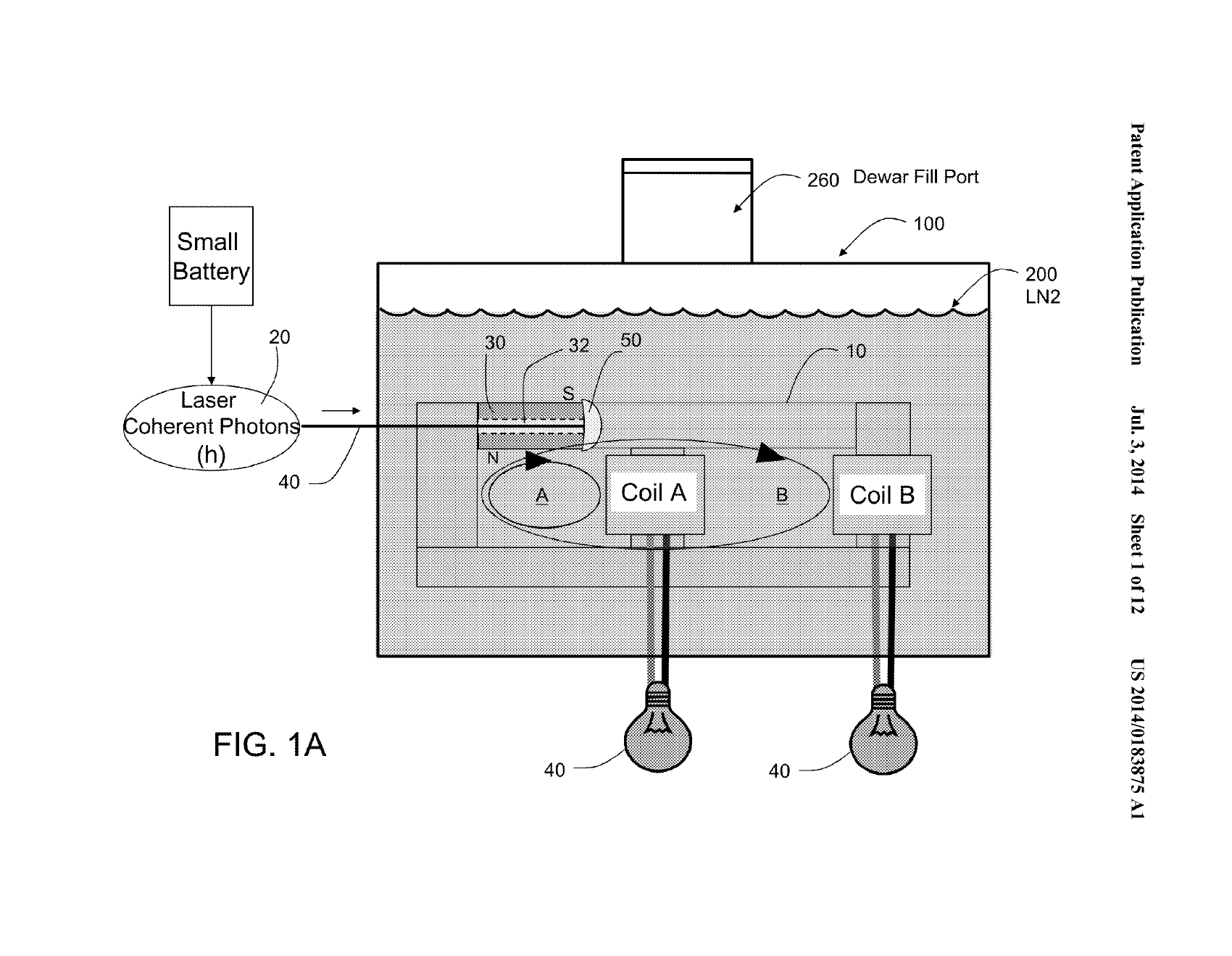
The application describes permanent-magnet flux passing through a circuit with two output paths. Coils occupy those paths. A change in flux through a coil can induce an electrical voltage. The proposed apparatus tries to create that change by altering the behaviour of the channel rather than by mechanically rotating an armature.
The central distinction is between a static field and a changing flux. A permanent magnet can establish a field, but the mere presence of a magnet does not explain a continuing electrical output. The switching process, its energy requirements and the response of the complete magnetic circuit must be included in the explanation.
What the superconducting channel is supposed to do
The application uses the phrase “vortex channel” for a superconducting structure intended to influence the flux path. It describes Type II superconductors and coated tubes, including an embodiment involving yttrium-barium-copper-oxide material. The document also discusses substrates, intermediate coatings and bundles of tubes.
These construction details belong to the applicant's proposed embodiments. They should not be read as a verified manufacturing specification or proof that a pictured channel achieved the claimed switching behaviour. A reader needs to distinguish three separate things: the material's superconducting properties, the proposed geometry, and the measured performance of a completed converter. Establishing the first does not automatically establish the other two.
The role of light
In the described operating cycle, illumination is intended to change the superconducting state and redirect magnetic flux. A light source and switching control are therefore part of the system. The patent's language of direct conversion should not make those inputs disappear from an energy balance.
The three introductory drawings, Figures 1A, 1B and 1C, are preserved in the visual record. Read them together. They show the overall arrangement and the different states used in the description, with coils on the output branches. The labels and arrows express the inventor's model of operation. They are not measured field maps.
Read the patent in layers
The abstract gives the compact proposal. The drawings identify components and states. The description develops possible arrangements. The claims define the subject matter sought in the application. These sections serve different purposes: a broad claim is not a table of achieved specifications, and a described alternative is not necessarily an additional prototype.
The application was published on 3 July 2014 and is associated with the later grant US9080557B2. The complete application PDF is available in Bench's source room, including the drawings and claims. That documentary record is more useful than treating the patent number as a seal of experimental validation.
Where the energy question sits
A meaningful performance assessment would account for illumination, control electronics, any required cooling and electrical output under load over a defined interval. Starting and ending stored energy matter as well. Magnetic, electrical and thermal transients can make a short demonstration look different from sustained operation.
Voltage on an open circuit is not the same quantity as delivered energy. A useful result would pair a described load with simultaneous measurements and a stated system boundary. A claimed improvement over another converter would also need a comparable baseline, including the same auxiliary requirements.
These are Bench's assessment questions, not tests supplied by the patent. The application describes a proposal; this dossier does not currently contain an independently reproduced, complete-system efficiency measurement for it.
Follow the components, not the headline
The most productive reading path is to trace one flux path in the first drawing, follow what changes between its operating states, and then locate the corresponding description in the preserved PDF. Keep the distinction between a proposed switching mechanism and demonstrated output throughout. The neighbouring energy dossiers provide comparisons in measurement and argument, not evidence that their mechanisms are shared.
Source notes & attribution
- https://patents.google.com/patent/US20140183875A1/en
Go deeper.
Primary reading1 min
US20140183875A1 — Method and apparatus for direct energy conversion
Read the preserved document, original figures and searchable text.
The visual record.
3 archived figures · open to inspectThe source room.
Everything readable here stays on StrangewellArchived texts preserve what the source said. They may contain historical, speculative, or promotional claims; inclusion is not verification.
Supporting documents (1)
“Captured” means saved for research; a full reading guide may still be pending.
Keep following.
Thematic connections, not evidence of a shared mechanism17 / Energy & machines
The bismuth battery
A thin-film device, its patent and its later reputation.
↗30 / Energy & machines
The Si₂HSb₂ amplifier
A crystalline material and an extraordinary amplification claim.
↗02 / Matter & materials
Chirality & spin
Follow the boundary between spin physics and extraordinary interpretations.
↗